How To Build Referee Lights
I've built several of these light boxes. This is the cheapest version I've been able to come up with. Should cost about $275 to build. It uses low power led lights. All the lights are wired in series. This allows the lights to come on after all refs signal in. No need for a master switch. After every attempt all refs should return their switch to the center position.
The led lights used in this design are pushing the limits of power usage that the 26g MIDI wire can provide. Don't use lights that draw more than 130ma each. I would also recommend not using a total of more than 150' of MIDI cable at one time (Three 50' foot runs).
Shopping List:
- Case
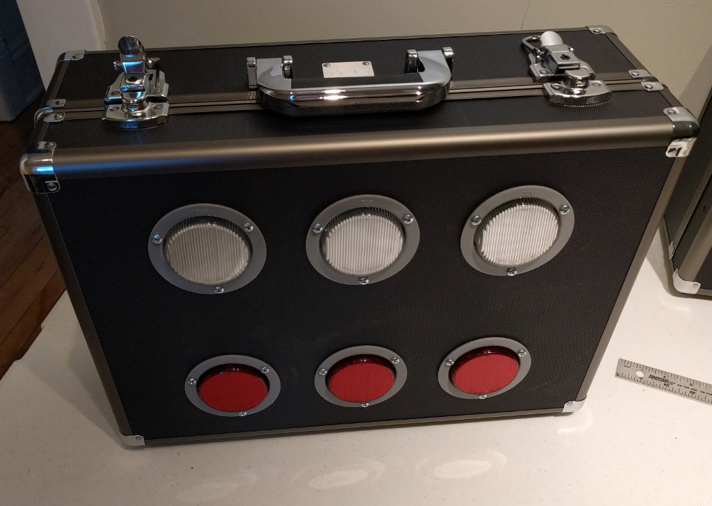
- (3) white, (3) red trailer lights
- (6) Light plugs
- 2.1MM DC socket
- (6) 5 pin sockets
- 3 Project boxes
- 12v power supply
- (3) DPDT ON-OFF-ON power switch
- 3 fender washers
- Blue, green, black, red, white wire. 20g or 22g will work.
- Heatshrink tubing.
- Red and white electrical tape.
- (3) MIDI couplers
- (6) 25' MIDI cables
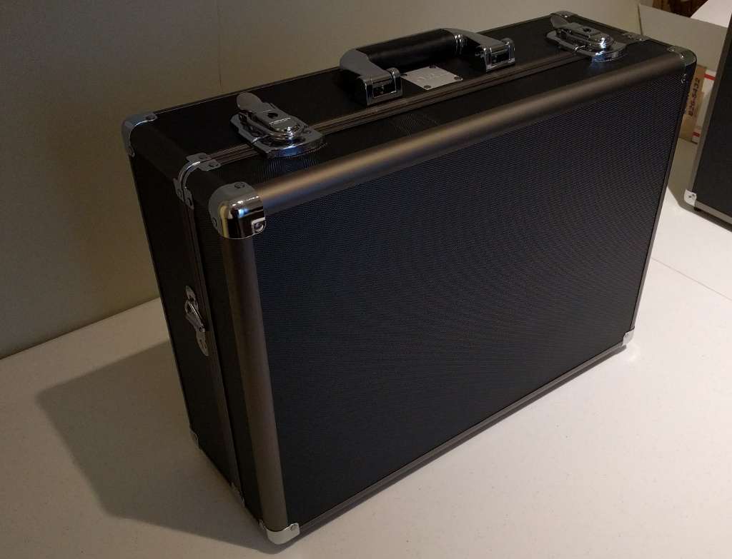
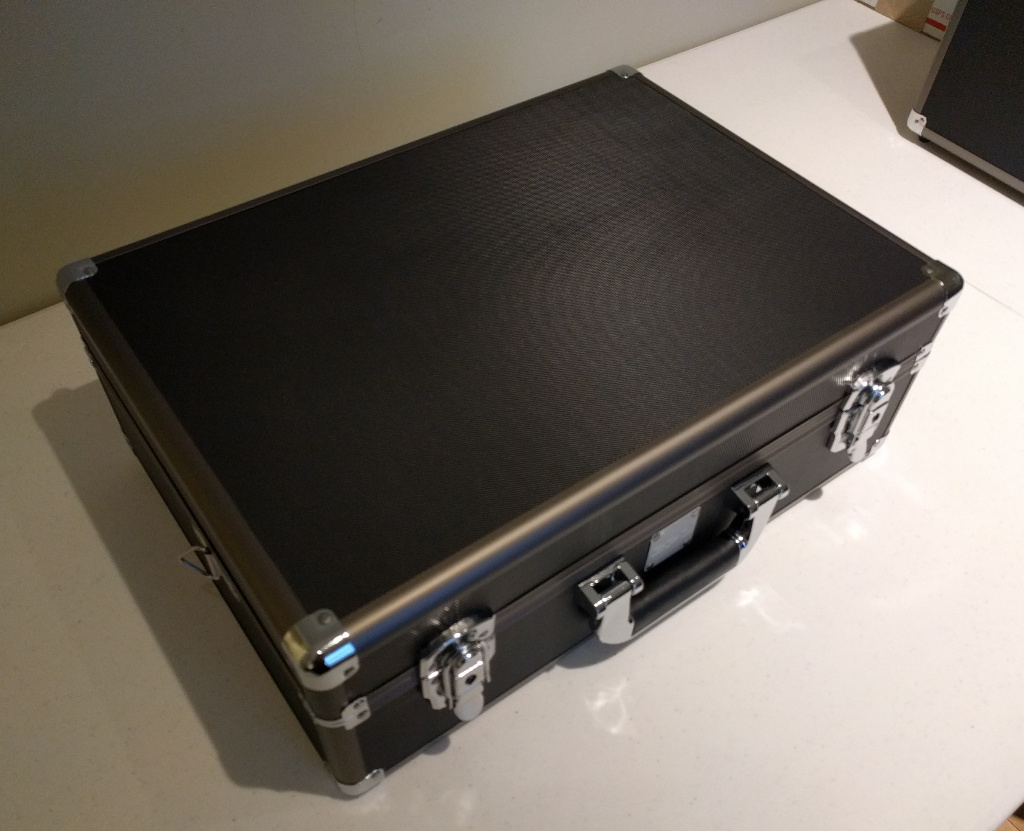
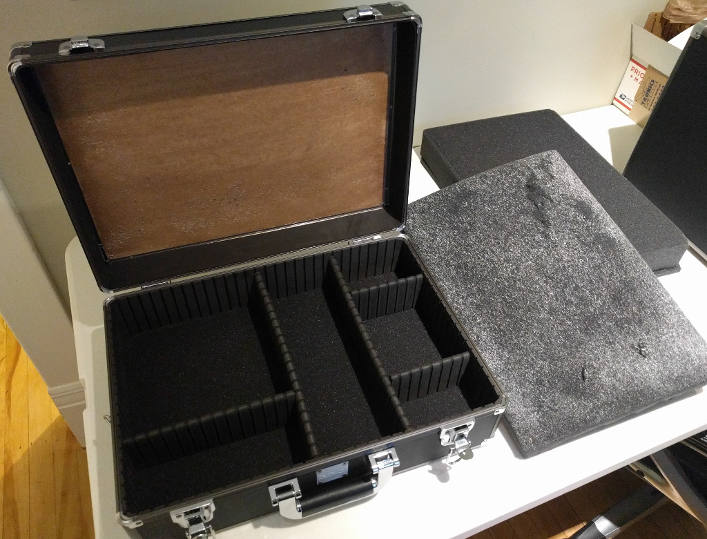
These cases are light duty ATA style cases. They are made out of 1/8 inch MDF
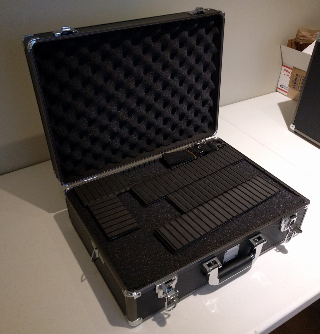
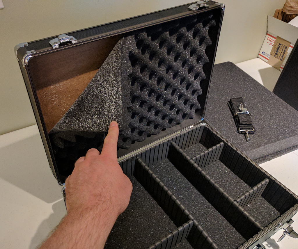
Start by removing the egg shell foam from the lid. This is where we are going to mount all of the electronics.
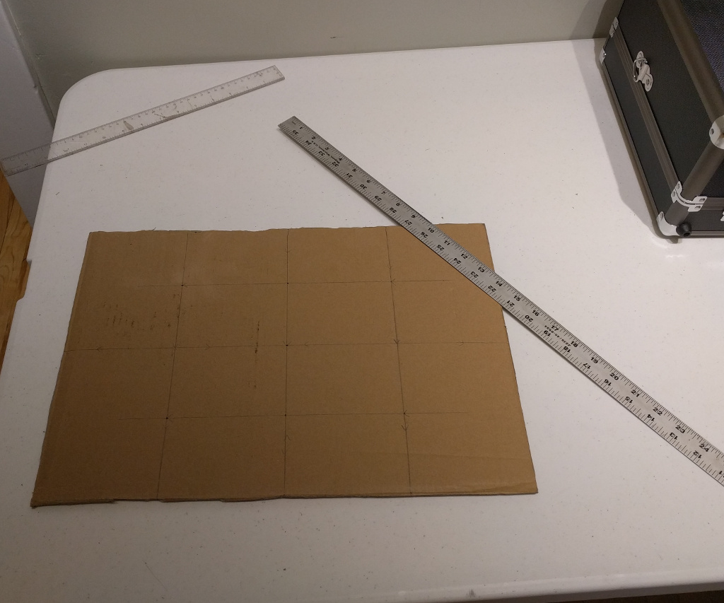
Since I'm making more than one box I cut a piece of cardboard the size of the lid. Layout the placement of the lights. Use the template to drill pilot holes.
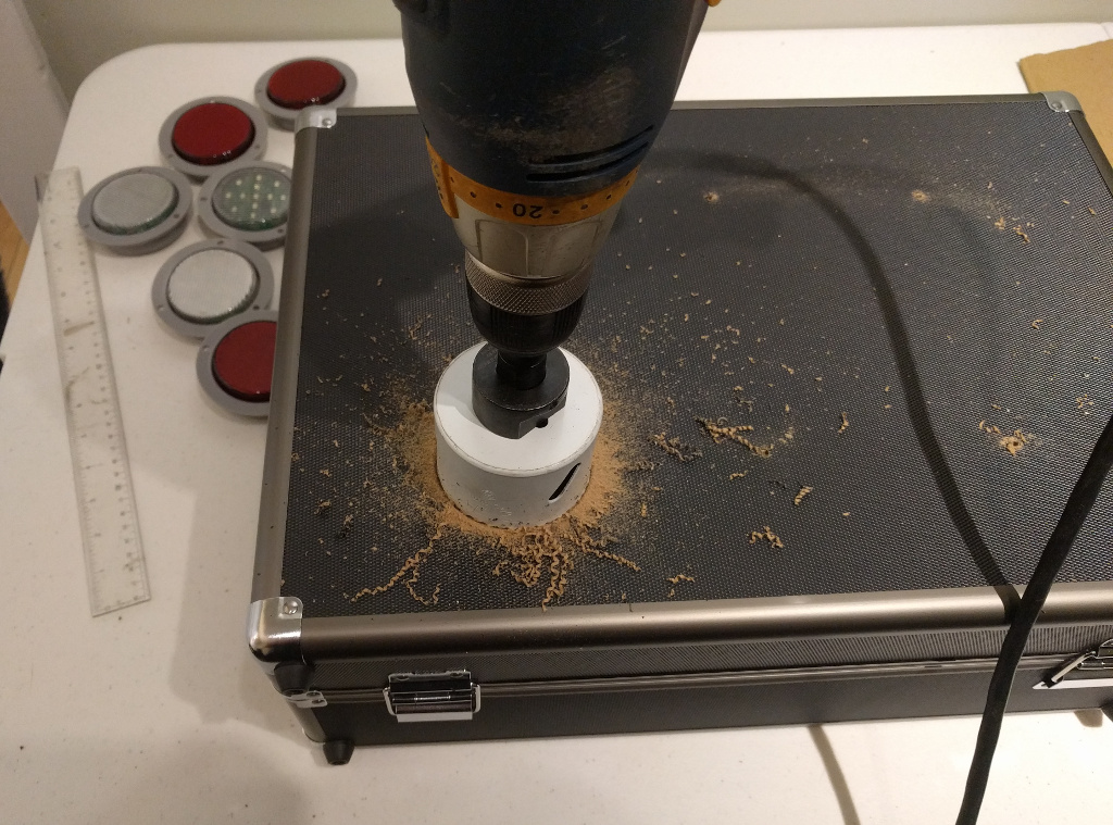
Use a 2 3/4th inch hole saw.
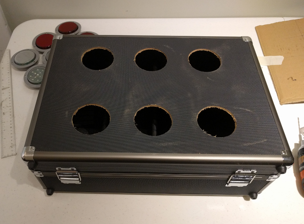
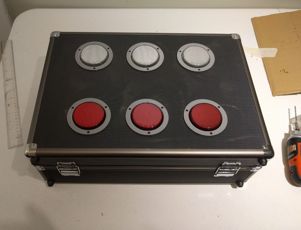
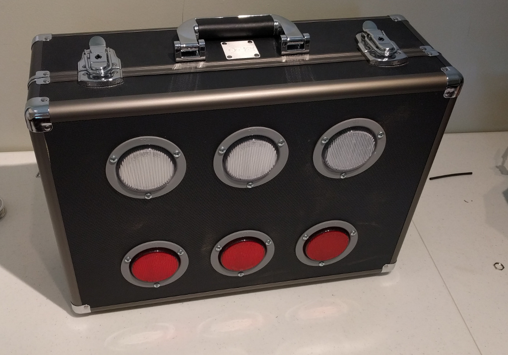
Test fit the lights.
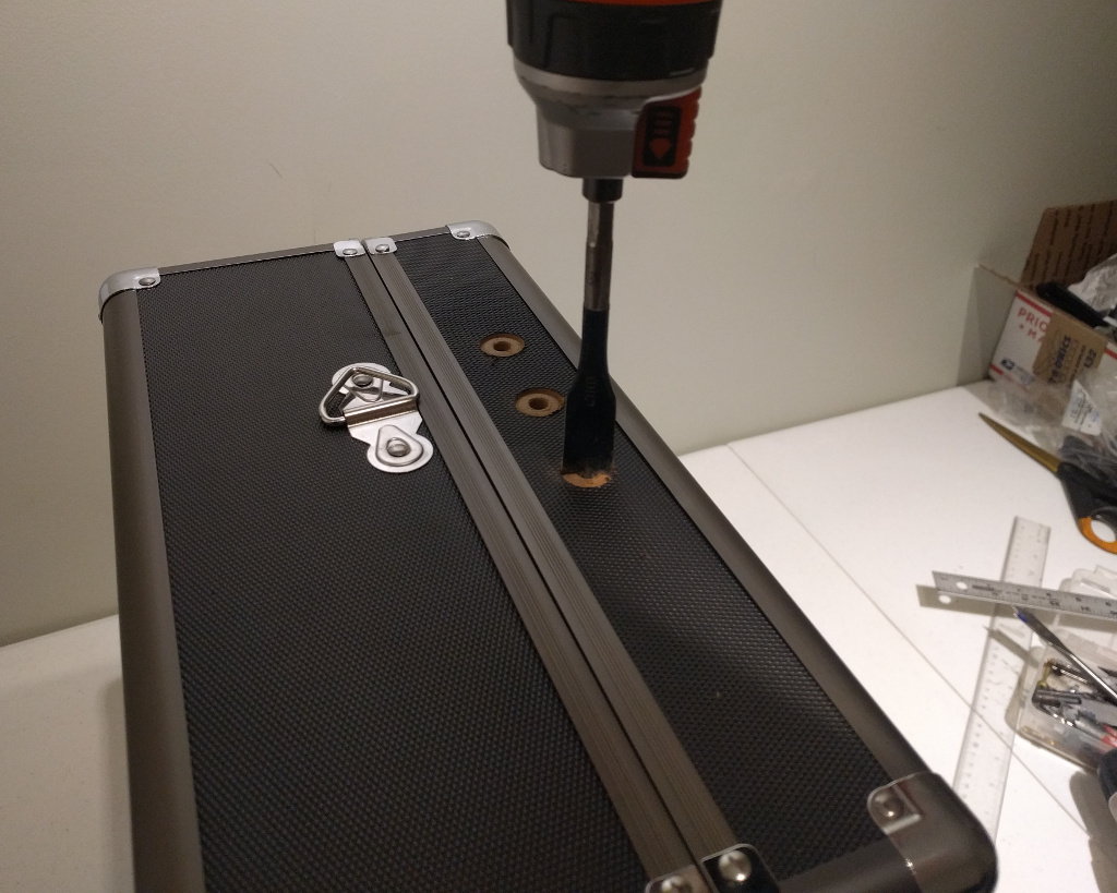
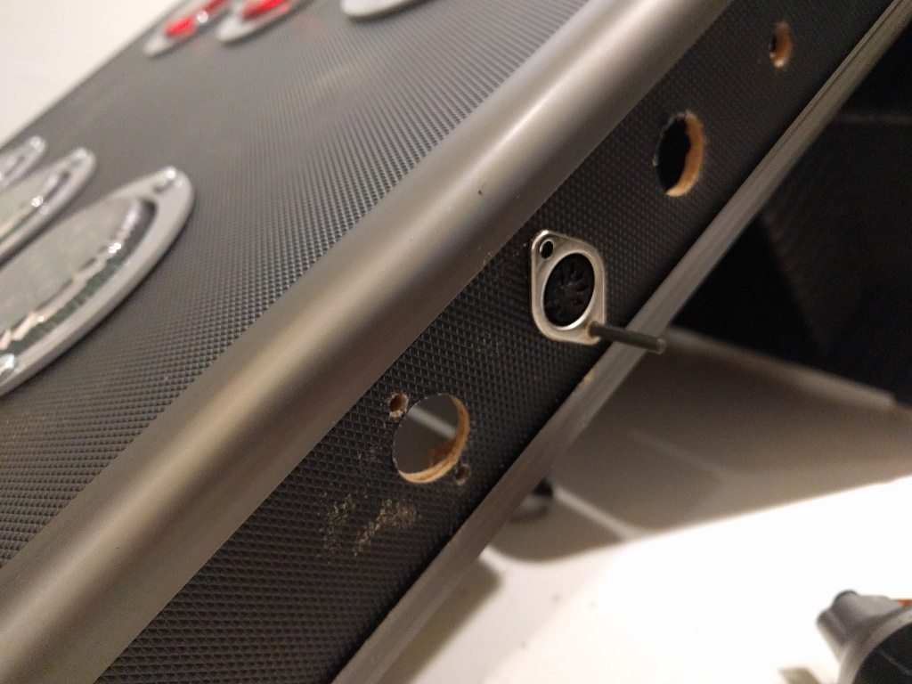
Drill three holes a few inches apart on the side of the lid. Use a 5/8th inch spade bit.
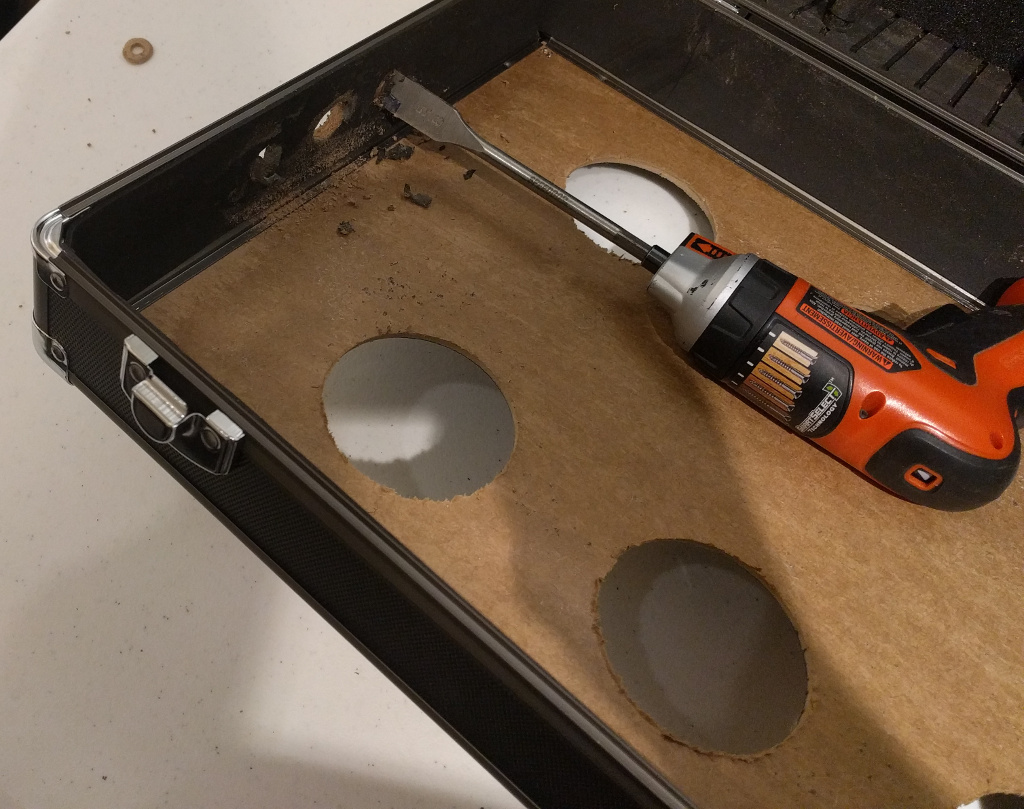
For a clean hole start on one side and finish on the other.
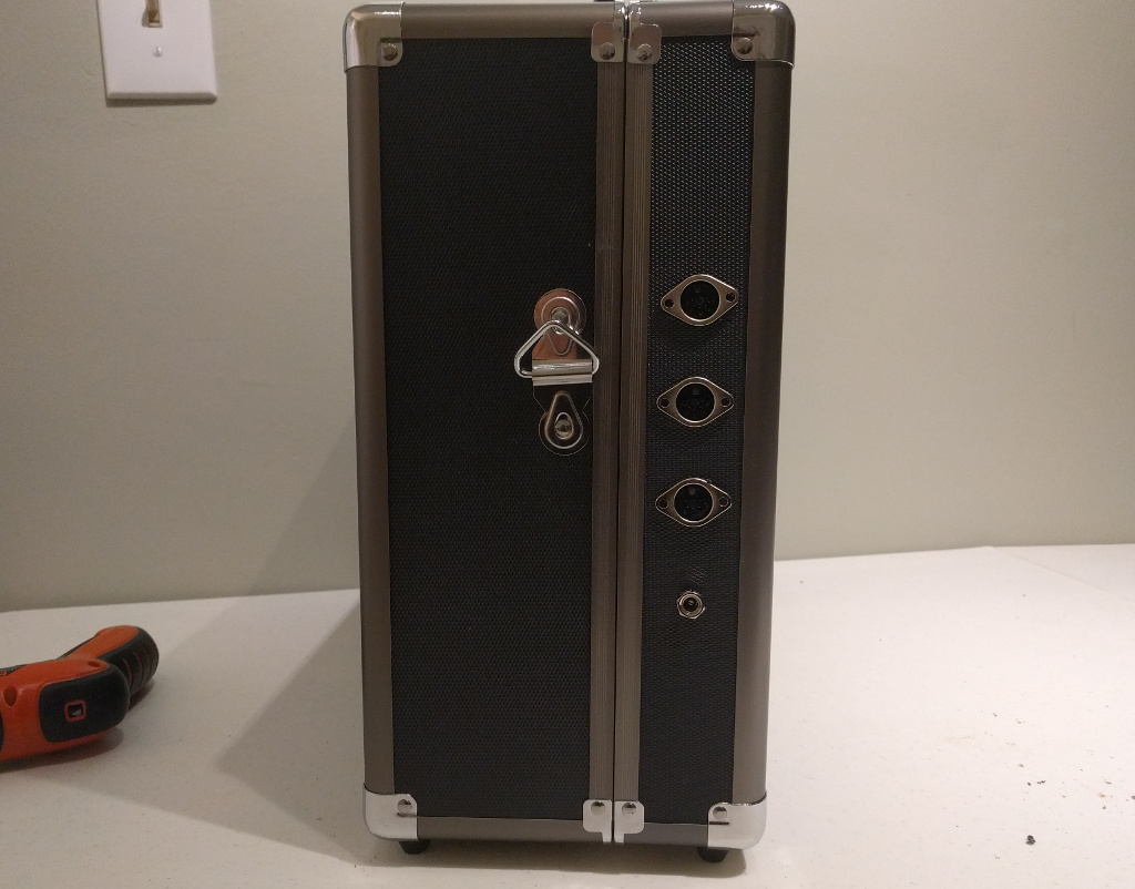
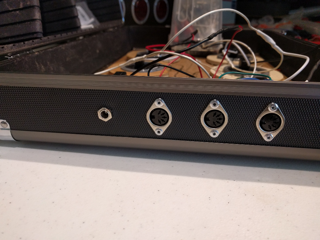
Drill another hole a few inches below the others for the power input. Test fit the MIDI sockets.
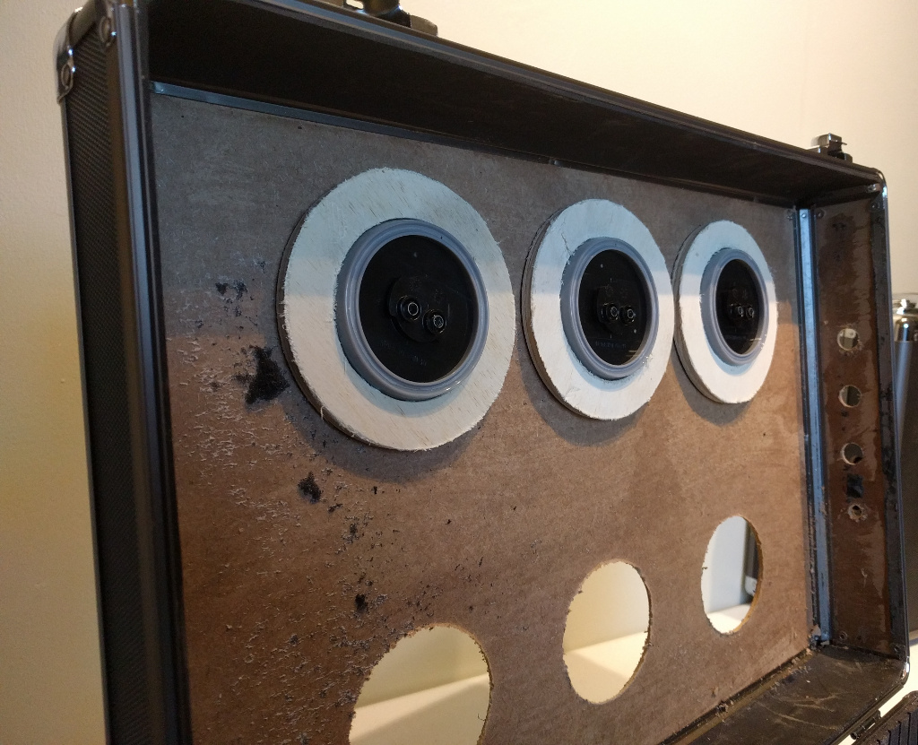
The MDF the case is made out of is a bit too flimsy to mount components to. I cut out some washers out of 1/4 inch plywood.
Use screws to mount lights.
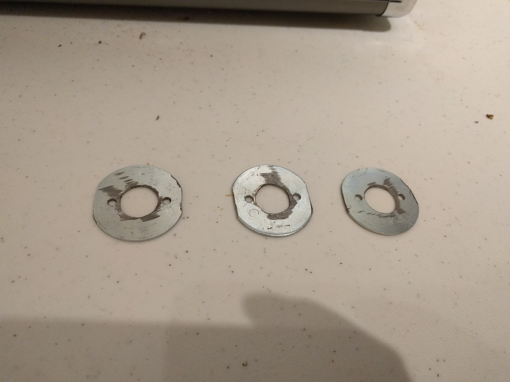
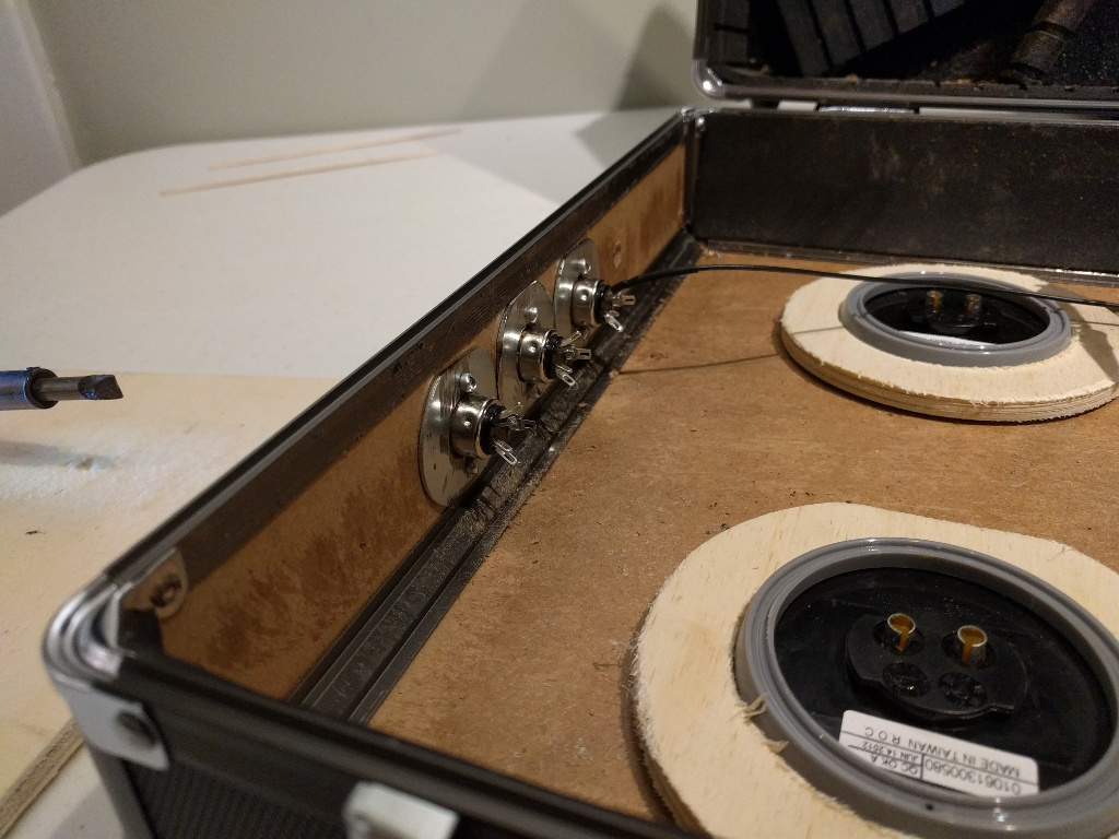
Need washers to help support the MIDI sockets. These started out as fender washers. Drilled 5/8th inch hole in the center. Drill 1/8th inch holes that line up with the socket holes. I had to grind the sides of these down a bit because they didn't fit in the space. A 9/16th inch washer would probably work.
Drill mounting holes in the case for the MIDI sockets.
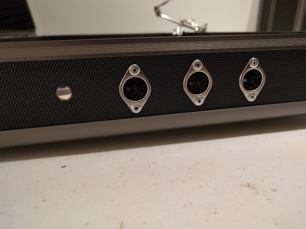
I use a rivet gun and 1/8th aluminum rivets to mount the MIDI sockets.
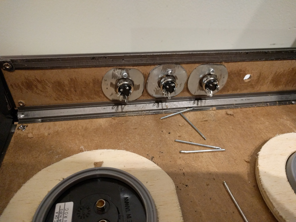
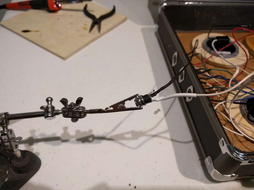
Solder a black wire onto pin 5 of the bottom MIDI socket. Cover solder joint with heatshrink tubing. The next time I do this step I will do solder lead wires onto the sockets before mounting them. Soldering on the sockets in this position was dificult.
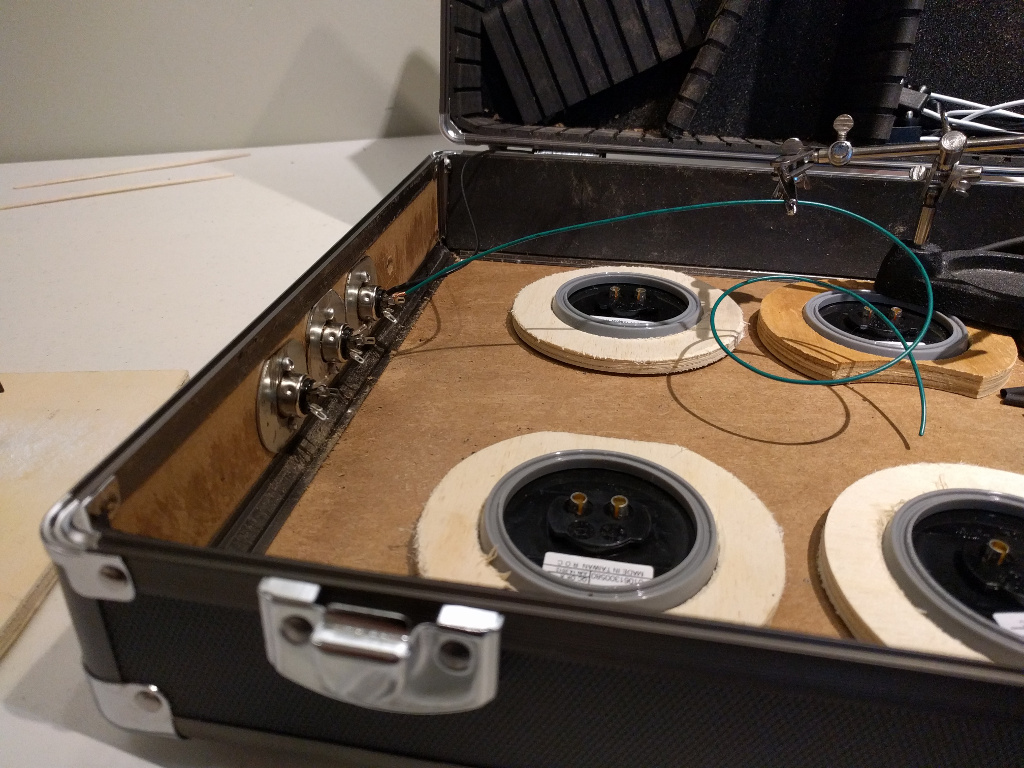
Solder a green wire pin 4 of the bottom MIDI socket.
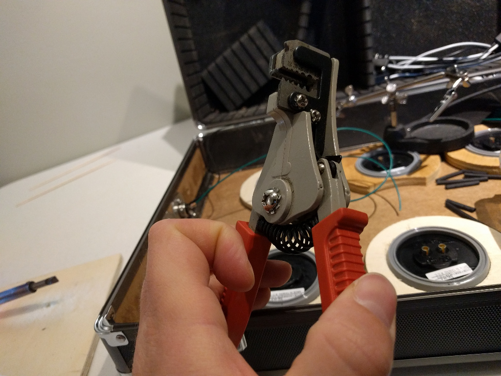
Auto stripers make striping all these small wires a lot easier.
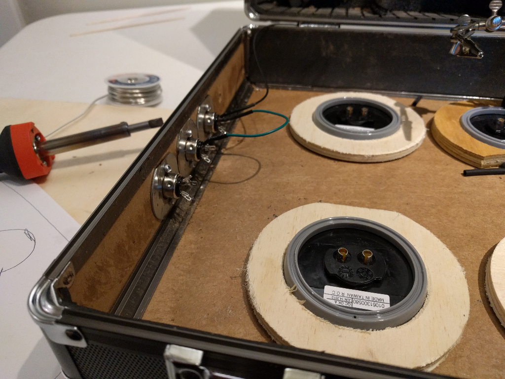
Solder the other end of the green wire to pin 5 of the center MIDI socket. Make sure to slide the heatshrink tubing onto the wire before soldering.
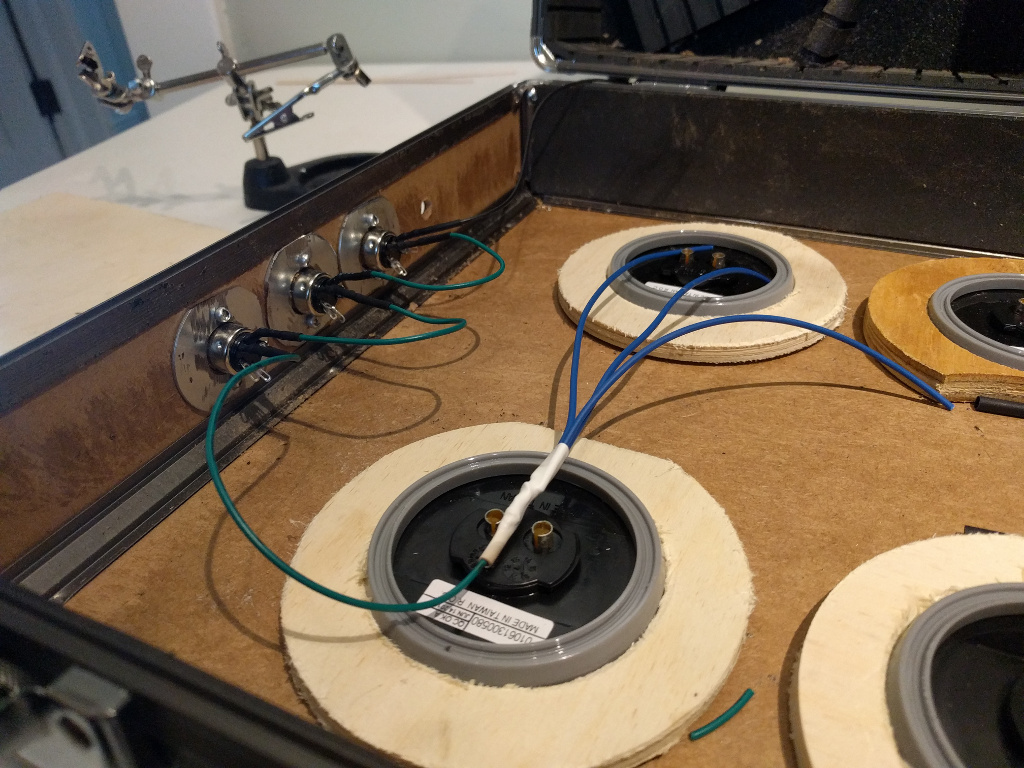
Solder a green wire from pin 4 of the center MIDI socket to pin 5 of the top MIDI socket. Solder a green wire onto pin 4 of the top MIDI socket. These green wires are for the flow of electricity that turns on all the lights. Split the last wire into three blue wires.
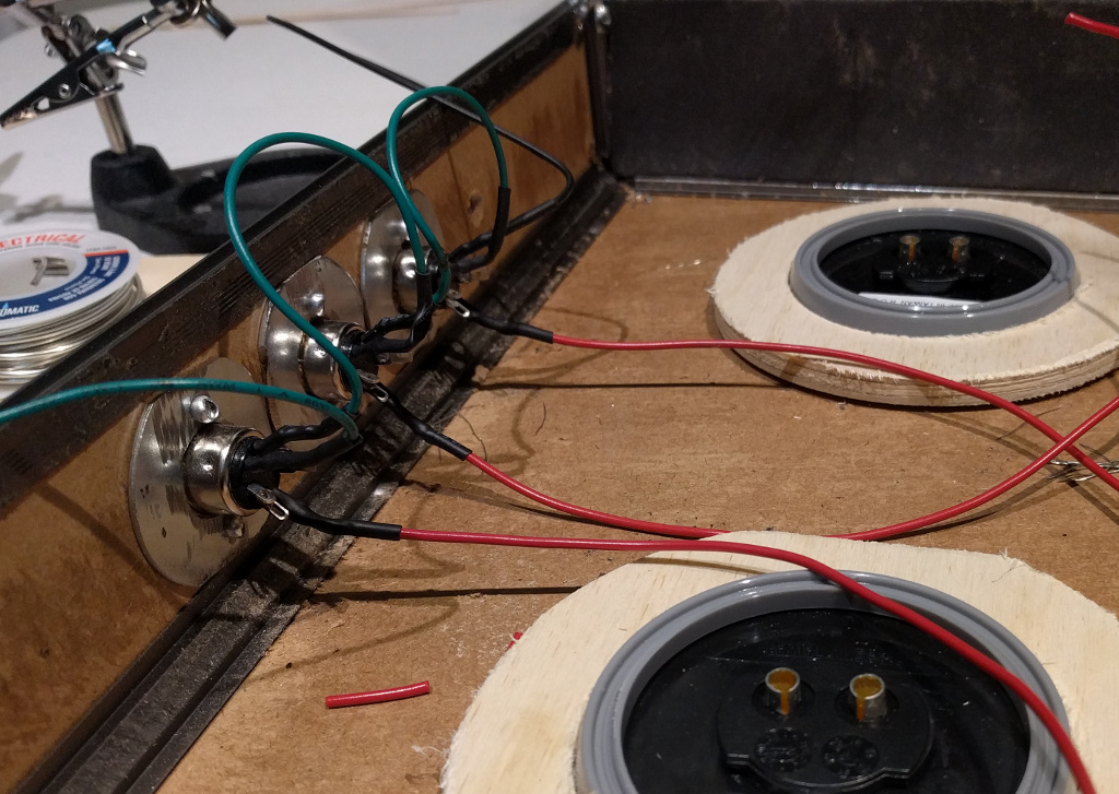
Solder a red wire onto pin 1 of each MIDI socket.
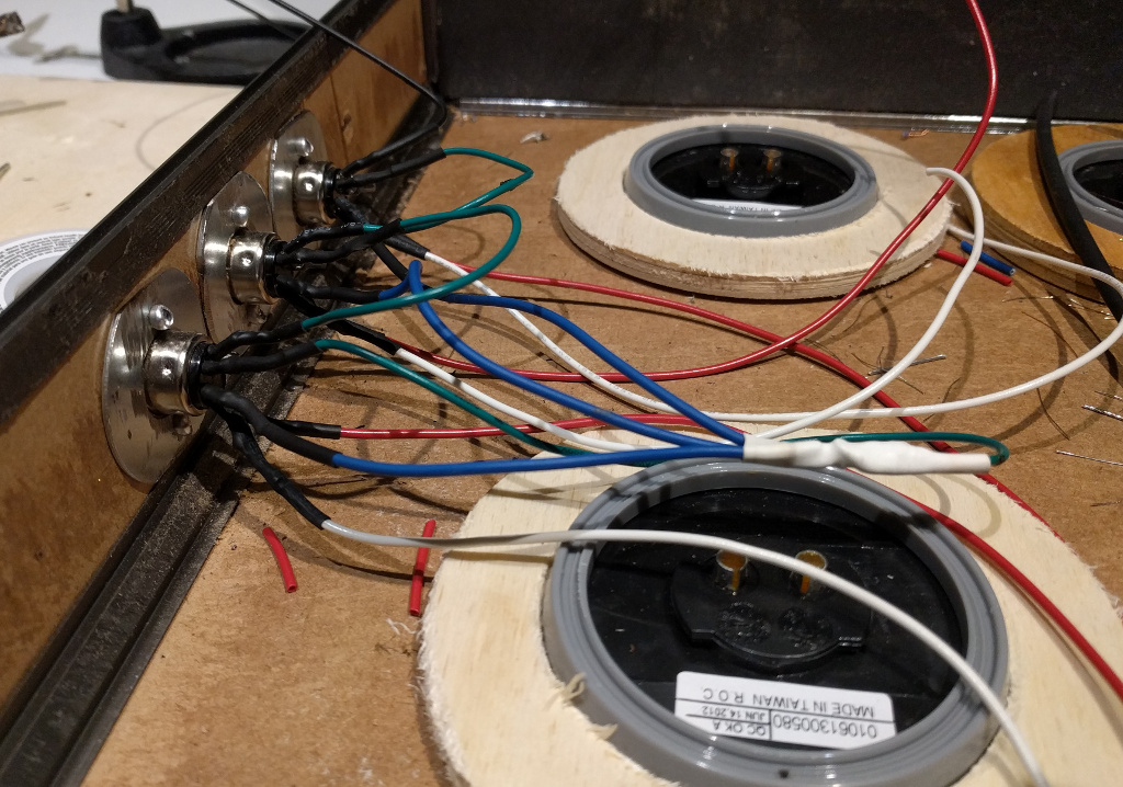
Solder a white wire on pin 2 of each MIDI socket. Solder blue wires that came off of the last socket onto pin 3 of each MIDI socket.
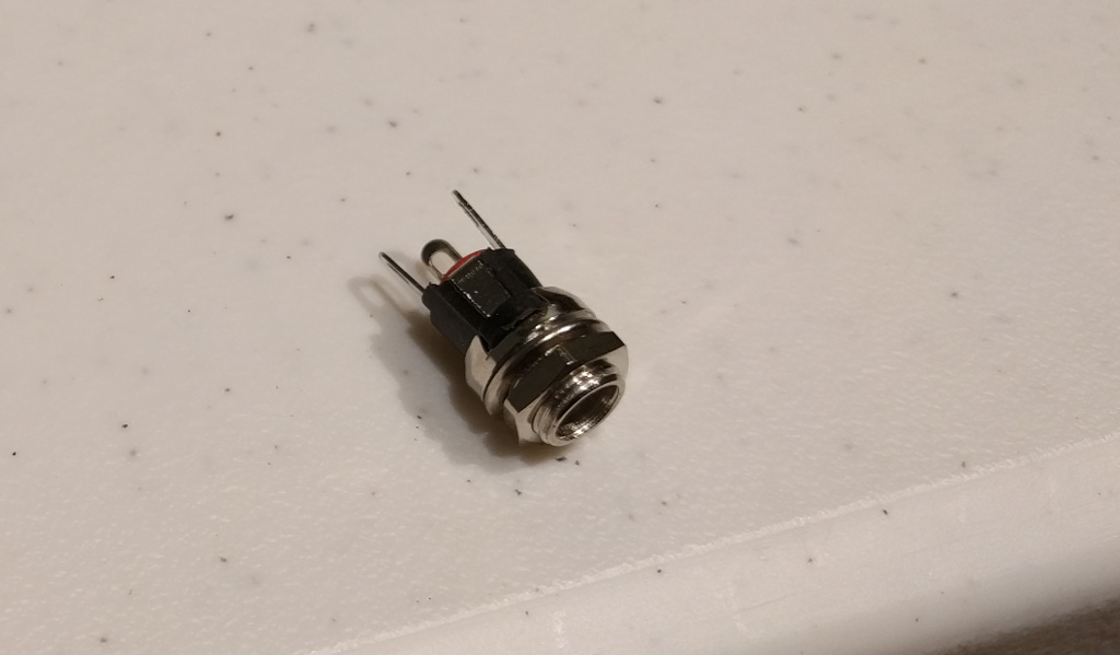
2.1MM coax power jack.
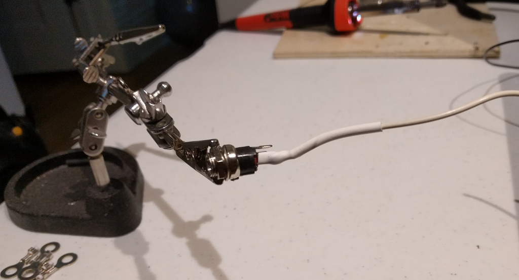
Solder a white wire onto one of the power pins.
Solder the black wire from pin 5 of bottom MIDI socket onto the other power pin on the power jack.
Mount power jack.
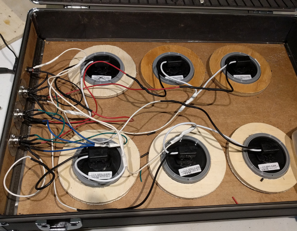
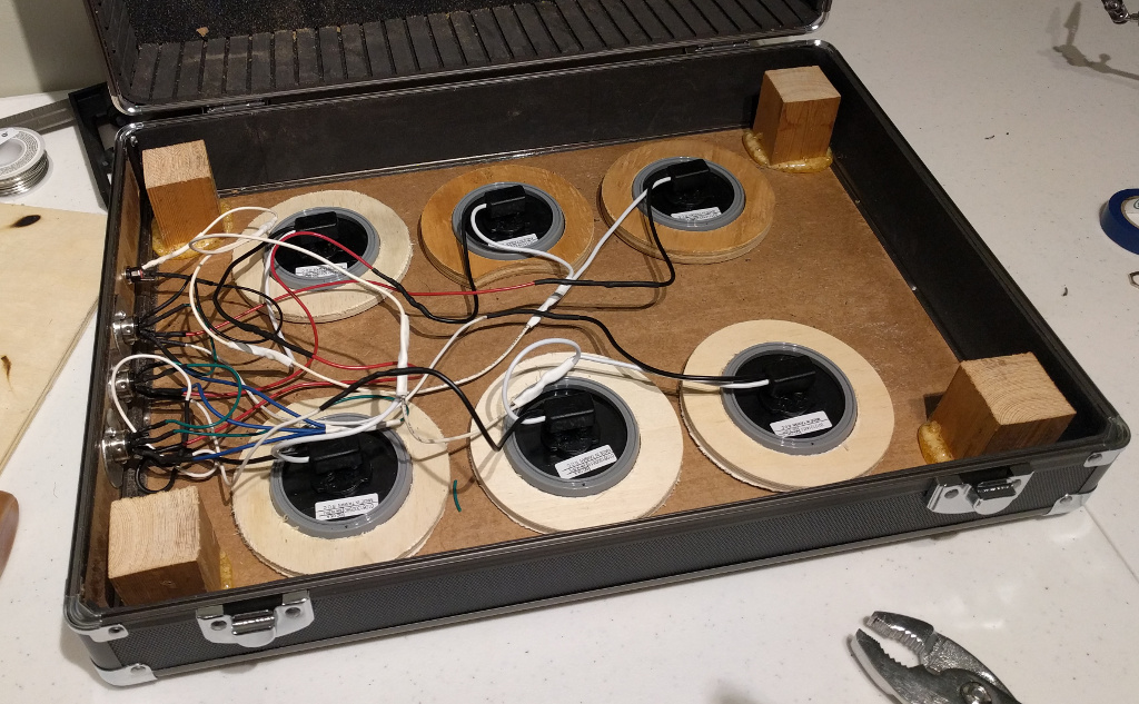
Attach light plugs to lights sockets. Connect all the white wires coming from the lights together and connect to white wire on power plug. Connect white wire from pin 2 to of bottom MIDI socket to black wire on top right light. Connect white wire from pin 2 of middle MIDI socket to black wire on top middle light. Connect white wire from pin 2 of top MIDI socket to black wire on top left light. Follow the same pattern to connect red wires to bottom lights.
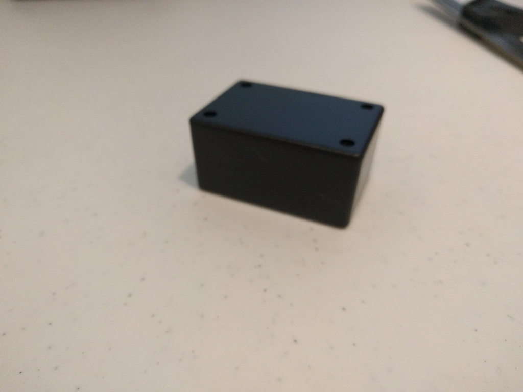
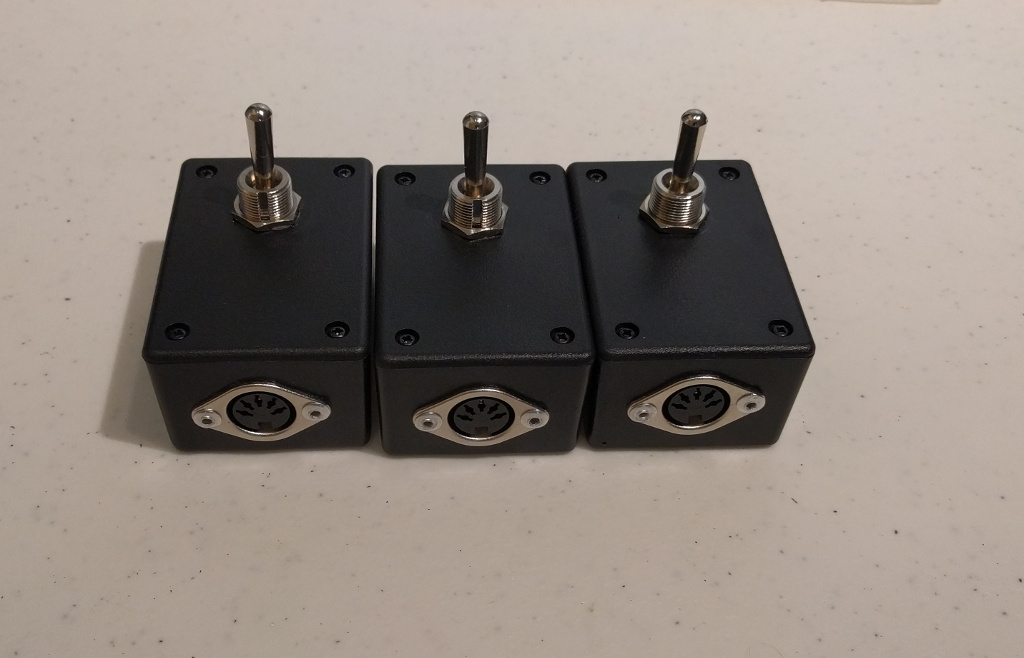
ABS project box to use for remotes.
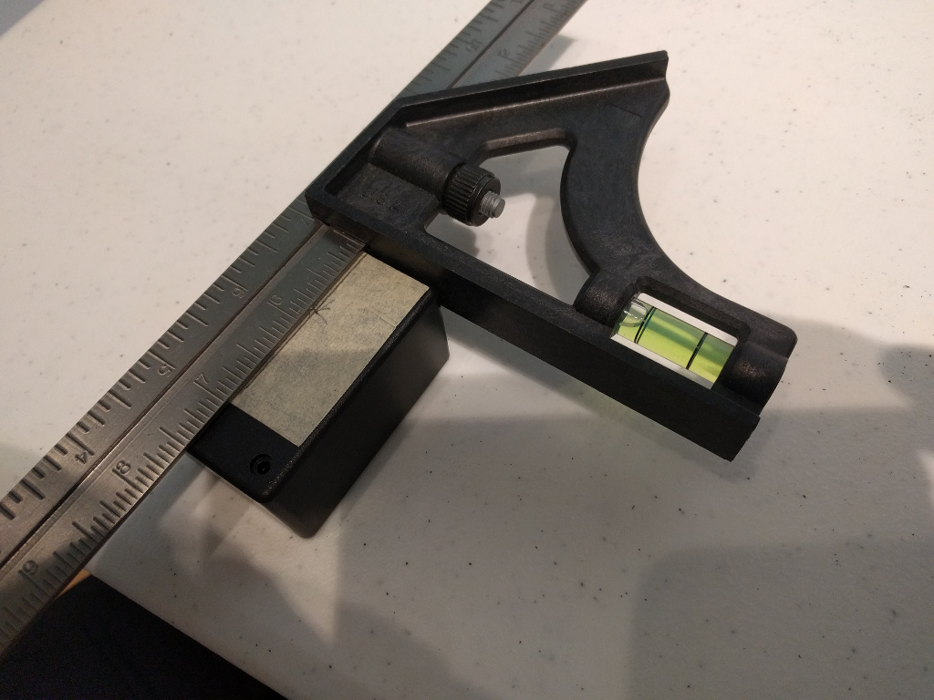
Mark a hole along the center, 13/16th on an inch from top.
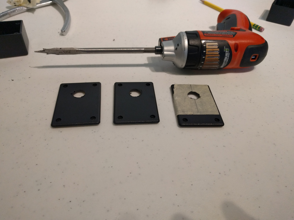
Drill out a 1/2 inch hole in the top of all of the project boxes.
Drill 5/8th inch holes in the center of the bottom of the project boxes.
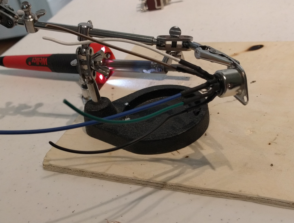
Solder wires onto the MIDI socket. Red wire pin 1. White wire pin 2. Blue wire pin 3. Green wire pin 4. Black wire pin 5.
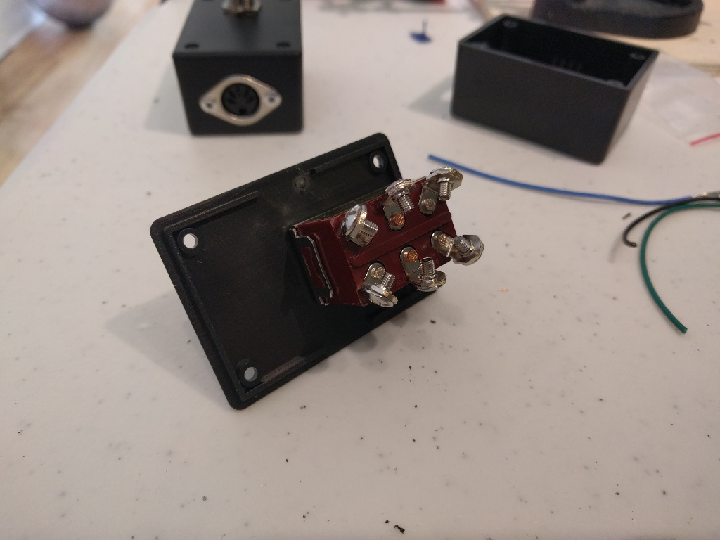
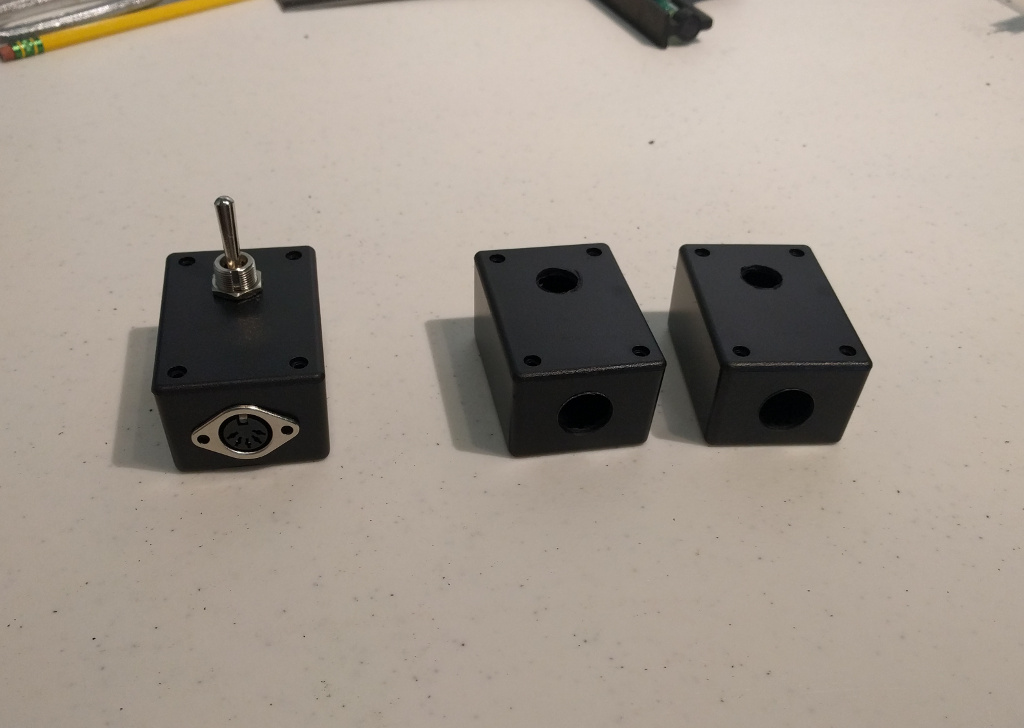
Switch mounted to the project box lid. These switches had cable guides on the end I had to cut off. I also had to bend the terminals out a bit to make them fit in the box.
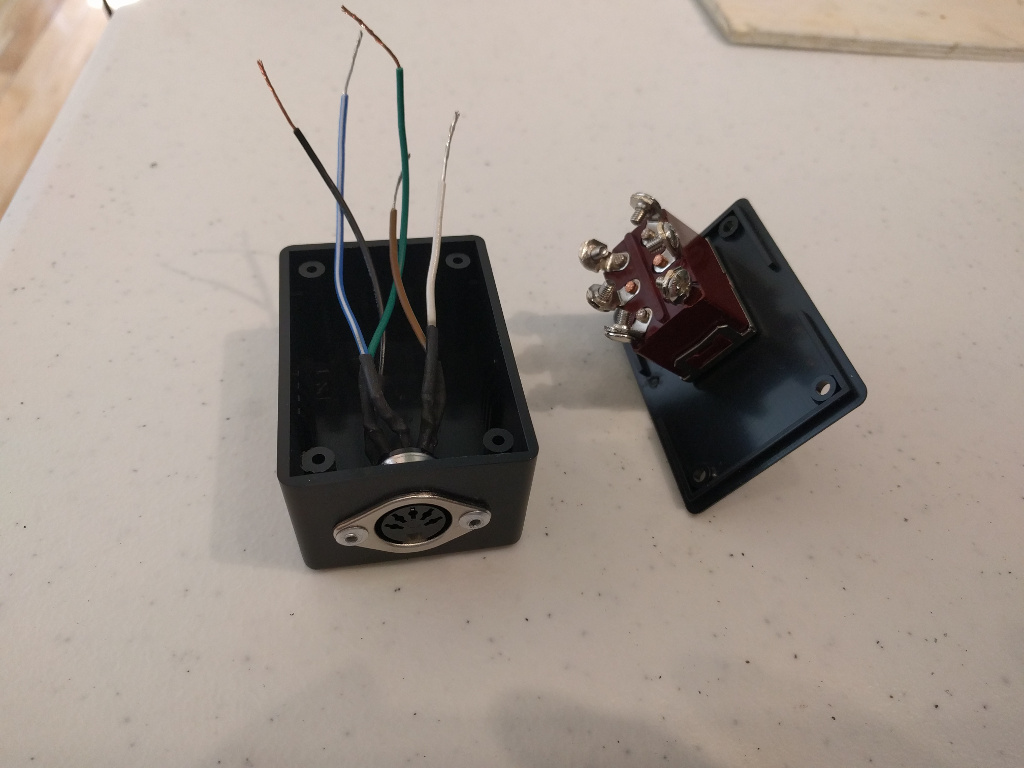
Mount MIDI socket in box. Connect with 1/8th inch aluminum rivets.
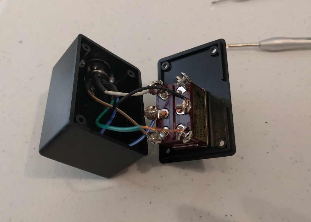
Keep in mind the switch is upside down in this picture. On one side of the switch. Connect white wire to the bottom terminal. Blue wire in the middle. Red wire on top. The switch closes the terminals on the opposite side of the switch position. Use a circuit testing to make sure everything is connected right.
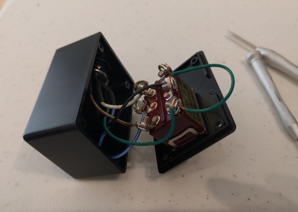
Connect the black wire to the middle terminal on the other side. Connect the green wire to both the top and bottom terminals on the other side. This allows power to flow to the whole system when the lights are in either position.
Do two more. Attach the covers.
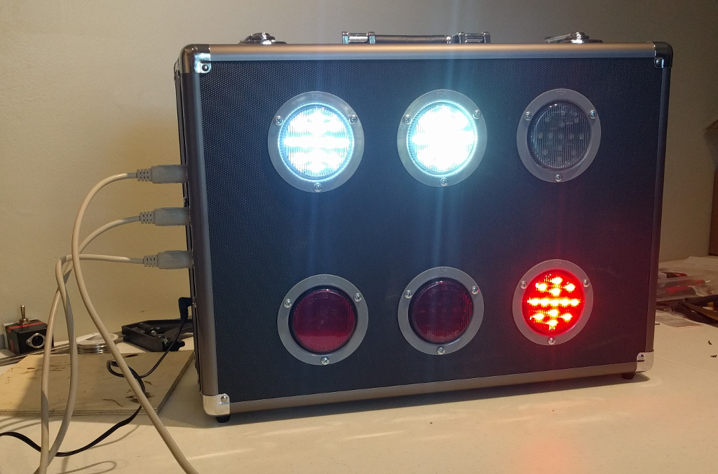
Plug everything in and see if it works.
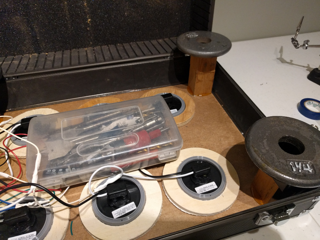
Cut some 2 inch long blocks of wood. Glue into the corners of the lid. I use some weights to hold down the blocks while drying.
Cut a sheet of 1/8th inch MDF. 17 1/2" x 12 1/4".
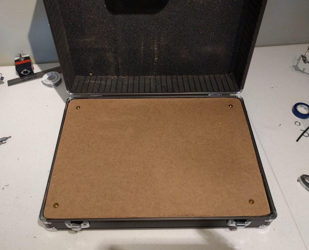
Screw onto the blocks.
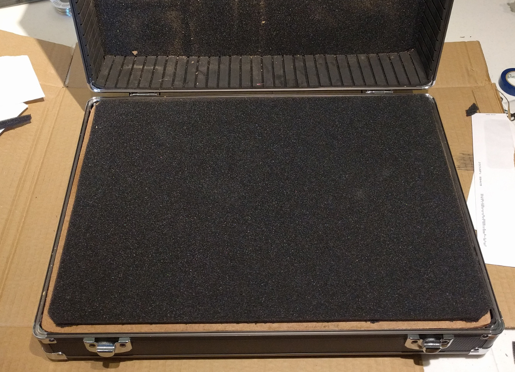
Use spray adhesive to attach the thin piece of extra foam that came with the case. Trim the edges so the case will close.
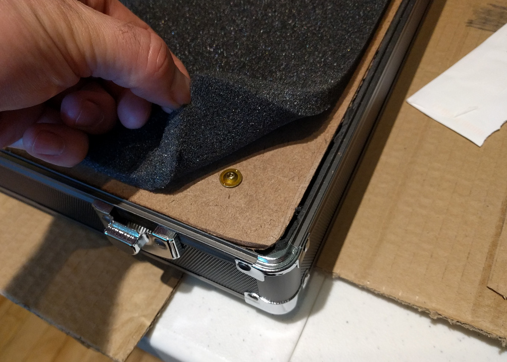
Don't glue the corners down, so you can take the cover off if needed.
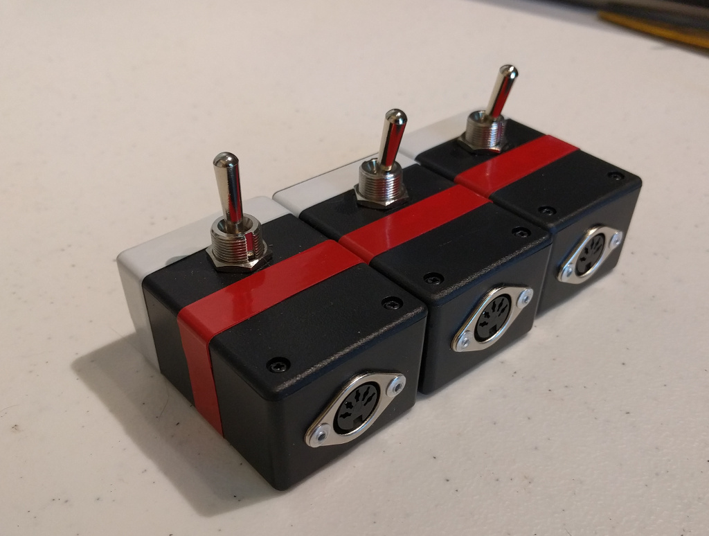
Put red and white tape on the boxes so refs know which way is which.
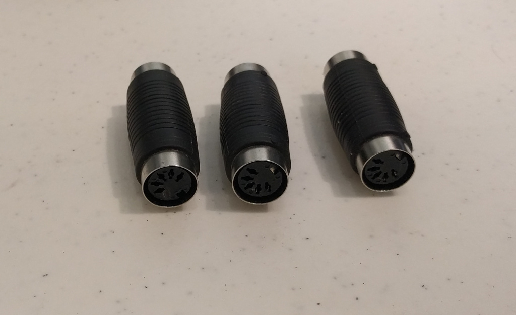
MIDI cables usually don't come in lengths longer than 25'. These connectors let you extend the cables. Since the lights are wired in series. The electricity for all the lights has to go through all the cables. Don't use an more cabling then you need to.
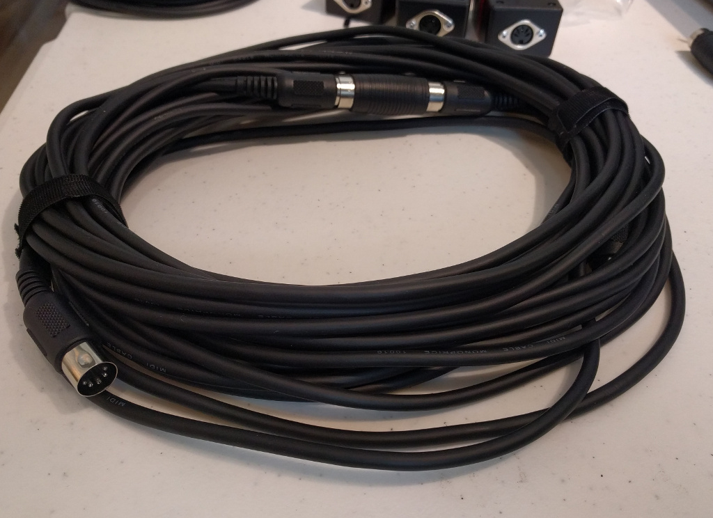
Two 25' cables wrapped up.
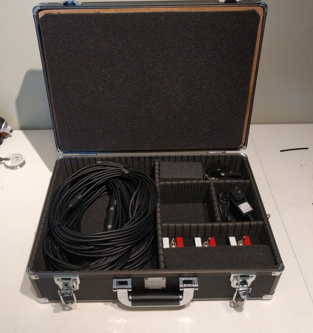
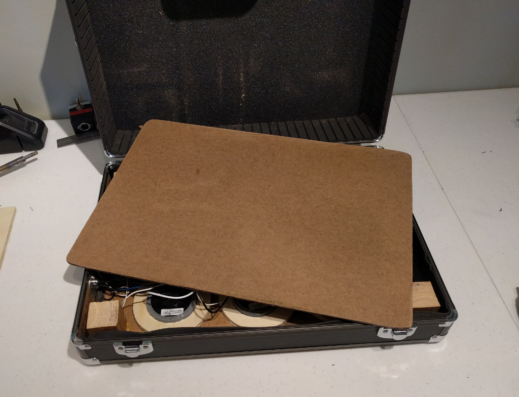
Everything packed into the case.